Acrylonitrile butadiene styrene, or ABS, (chemical formula (C8H8· C4H6·C3H3N)n) is a common thermoplastic used to make light, rigid, molded products such as piping, plastic for electronics component, gear, automotive body parts, wheel covers, enclosures, protective head gear, toys, small appliance housings and power tools applications (hair dryers, blenders, food processors, lawnmowers, etc.
ABS is the polymerization of Acrylonitrile, Butadiene, and Styrene monomers, the proportions can vary from 15 to 35% acrylonitrile, 5 to 30% butadiene and 40 to 60% styrene. The result is a long chain of polybutadiene criss-crossed with shorter chains of poly(styrene-co-acrylonitrile). The nitrile groups from neighboring chains, being polar, attract each other and bind the chains together, making ABS stronger than pure polystyrene. this polymers can be engineered by the manufacturer togive a range of physical properties, depending on the ratio of the monomeric constituents and the molecular level connectivity. Typically, a styrene-acrylonitrile glassy phase is toughened by an amorphous butadiene/butadiene-acrylonitrile rubber phase.
ABS Properties
ABS polymers are resistant to aqueous acids, alkalis, concentrated hydrochloric and phosphoric acids, alcohols and animal, vegetable and mineral oils, but they are swollen by glacial acetic acid, carbon tetrachloride and aromatic hydrocarbons and are attacked by concentrated sulfuric and nitric acids. They are soluble in esters, ketones and ethylene dichloride.
Injection molding processing conditions
Melt Temperature
200 - 280 C (392 - 536 F); Aim: 230 C (446 F). Average value: 232 °C
Feed Temperature 191 - 210 °C 375 - 410 °F Average value: 200 °C
Rear Barrel Temperature 149 - 227 °C 300 - 441 °F Average value: 196 °C
Middle Barrel Temperature 177 - 250 °C 350 - 482 °F Average value: 214 °C
Front Barrel Temperature 191 - 249 °C 375 - 480 °F Average value: 225 °C
Nozzle Temperature 191 - 274 °C 375 - 525 °F Average value: 227 °C
Adapter Temperature 221 - 241 °C 430 - 465 °F Average value: 231 °C
Mold Temperature 25 - 80 C (77 - 176 F). Mold temperatures control the gloss properties; lower mold temperatures produce lower gloss levels.
Dry Time 2.00 - 24.0 hour 2.00 - 24.0 hour Average value: 4.01 hour
Material Injection Pressure 50 - 100 MPa, Average value: 45.9 MPa
Back Pressure 0.172 - 2.00 MPa 24.9 - 290 psi Average value: 0.702 MPa
Shot Size 30.0 - 80.0 % 30.0 - 80.0 % Average value: 57.9 %
Vent Depth 0.00380 - 0.00760 cm 0.00150 - 0.00299 in Average value: 0.00487 cm G
Screw Speed 25.0 - 100 rpm 25.0 - 100 rpm Average value: 63.7 rpm
Physical Properties
Density 0.350 - 1.26 g/cc 0.0126 - 0.0455 lb/in³ Average value: 1.05 g/cc
Water Absorption 0.0500 - 2.30 % 0.0500 - 2.30 % Average value: 0.565 %
Moisture Absorption at Equilibrium 0.200 - 0.450 % 0.200 - 0.450 % Average value: 0.339 %
Water Absorption at Saturation 0.300 % 0.300 % Average value: 0.300 %
Maximum Moisture Content 0.150 0.150 Average value: 0.150
Linear Mold Shrinkage 0.00240 - 0.00800 cm/cm 0.00240 - 0.00800 in/in Average value: 0.00536 cm/cm
Linear Mold Shrinkage, Transverse 0.00250 - 0.00700 cm/cm 0.00250 - 0.00700 in/in Average value: 0.00519 cm/cm
Melt Flow 0.0800 - 56.7 g/10 min 0.0800 - 56.7 g/10 min Average value: 10.1 g/10 min
ABS Resistance:
Excellent resistance (no attack) to Glycerine, Inorganic Salts, Alkalis, Many Acids, Most Alcohols and Hydrocarbons
Limited resistance (moderate attack and suitable for short term use only) to Weak Acids
Poor resistance (not recommended for use with) Strong Acids and Solvents, Ketones, Aldehydes, Esters, and some Chlorinated Hydrocarbons.
Mechanical Properties
Hardness, Rockwell R 90.0 - 119 90.0 - 119 Average value: 107
Tensile Strength, Ultimate 20.0 - 43.0 MPa 2900 - 6240 psi Average value: 31.8 MPa
Tensile Strength, Yield 20.0 - 65.0 MPa 2900 - 9430 psi Average value: 43.5 MPa
Elongation at Break 2.40 - 110 % 2.40 - 110 % Average value: 27.0 %
Elongation at Yield 1.70 - 6.00 % 1.70 - 6.00 % Average value: 3.00 %
Modulus of Elasticity 1.52 - 6.10 GPa 220 - 885 ksi Average value: 2.34 GPa
Flexural Modulus 1.50 - 25.0 GPa 218 - 3630 ksi Average value: 2.47 GPa
Flexural Yield Strength 40.0 - 95.1 MPa 5800 - 13800 psi Average value: 69.0 MPa
Izod Impact, Unnotched 0.981 J/cm - NB 1.84 ft-lb/in - NB Average value: 3.46 J/cm
Izod Impact, Unnotched (ISO) 39.2 kJ/m² - NB 18.7 ft-lb/in² - NB Average value: 39.2 kJ/m²
Izod Impact, Unnotched Low Temp 0.600 - 2.00 J/cm 1.12 - 3.75 ft-lb/in Average value: 1.28 J/cm
Izod Impact, Notched, Low Temp (ISO) 5.00 - 14.0 kJ/m² 2.38 - 6.66 ft-lb/in² Average value: 8.18 kJ/m²
Charpy Impact Unnotched 2.00 J/cm² - NB 9.52 ft-lb/in² - NB Average value: 14.3 J/cm²
Charpy Impact, Notched, Low Temp 0.200 - 1.60 J/cm² 0.952 - 7.61 ft-lb/in² Average value: 0.831 J/cm²
Charpy Impact, Unnotched Low Temp 0.300 J/cm² - NB 1.43 ft-lb/in² - NB Average value: 7.15 J/cm²
Charpy Impact, Notched 0.500 - 14.0 J/cm² 2.38 - 66.6 ft-lb/in² Average value: 2.18 J/cm²
Gardner Impact 1.80 - 22.6 J 1.33 - 16.7 ft-lb Average value: 15.5 J
Falling Dart Impact 2.82 - 37.6 J 2.08 - 27.7 ft-lb Average value: 22.7 J
Impact Test 5.40 - 58.0 J 3.98 - 42.8 ft-lb Average value: 40.4 J
Tensile Creep Modulus, 1 hour 2000 - 2500 MPa 290000 - 363000 psi Average value: 2200 MPa Grade Count:6
Tensile Creep Modulus, 1000 hours 1150 - 1900 MPa 167000 - 276000 psi Average value: 1550 MPa Grade Count:11
Izod Impact, Notched @ -40°C 0.350 - 3.95 J/cm 0.656 - 7.40 ft-lb/in Average value: 2.32 J/cm
Izod Impact, Notched 0.100 - 6.40 J/cm 0.187 - 12.0 ft-lb/in Average value: 2.32 J/cm
Izod Impact, Notched, Low Temp 0.500 - 2.14 J/cm 0.937 - 4.01 ft-lb/in Average value: 0.792 J/cm
Izod Impact, Notched (ISO) 5.00 - 25.0 kJ/m² 2.38 - 11.9 ft-lb/in² Average value: 15.5 kJ/m²
Standard and References
D 2282 Spesification for ABS Plastic Pipe
D 2468 Spesification for ABS Plastic Pipe fitting
D 3965-05 Standard Specification for Rigid Acrylonitrile-Butadiene-Styrene (ABS) Materials for Pipe and Fittings
D 1527 - 99(2005) Standard Specification for Acrylonitrile-Butadiene-Styrene (ABS) Plastic Pipe
ASTM D4673 - 02 Standard Classification System for Acrylonitrile-Butadiene-Styrene (ABS) Plastics and Alloys Molding and Extrusion Materials
ASTM D3641 - 02 Standard Practice for Injection Molding Test Specimens of Thermoplastic Molding and Extrusion Materials
what does polymer mean?
Polymer means many monomers. Sometimes polymers are also known as macromolecules or large-sized molecules. Usually, polymers are organic but not necessarily
we can what is monomer and polymer?
monomer
Monomers are molecules typically about 4-10 atoms in size, reactive in that they bond readily to other monomers in a process called polymerization. Polymers and their polymerization processes are so diverse that a variety of different systems exist to classify them. One major type of polymerization is condensation polymerization, where reacting molecules release water as a byproduct. This is the means by which all proteins are formed.
The monomer molecules may be all alike, or they may represent two, three, or more different compounds. Usually at least 100 monomer molecules must be combined to make a product that has certain unique physical properties—such as elasticity, high tensile strength, or the ability to form fibres—that differentiate polymers from substances composed of smaller and simpler molecules; often, many thousands of monomer units are incorporated in a single molecule of a polymer (Encyclopedia of Britannica)
Polymer definition.
Polymers are molecules which consist of a long, repeating chain of smaller units called monomers. Polymers have the highest molecular weight among any molecules, and may consist of billions of atoms. Human DNA is a polymer with over 20 billion constituent atoms. Proteins, or the polymers of amino acids, and many other molecules that make up life are polymers. Polymers are the largest and most diverse class of known molecules. They even include plastics.(wise geek.com)
a chemical reaction in which two or more molecules combine to form larger molecules that contain repeating structural unit.
polymer chemistry, polymerization is a process of reacting monomer molecules together in a chemical reaction to form three-dimensional networks or polymer chains (wikipedia.com)
How Polymer formed?
To get a clear idea of the way polymers are formed, you need to look more closely at the monomer molecules! There are many monomer molecules. Here are some examples from materialworld.org, 
Chain-growth polymerization or addition polymerization involves the linking together of molecules incorporating double or triple chemical bonds. These unsaturated monomers (the identical molecules which make up the polymers) have extra internal bonds which are able to break and link up with other monomers to form the repeating chain.
The highlighted areas show the side groups on these monomer molecules. These groups give the polymer chain some of its properties.
The double bond, however, is the vital feature that allows these monomers to form the long polymer chains.
Chemical Bond
to learn more about polymerization, we must know about chemical bonding concept
A chemical bond is the physical process responsible for the attractive interactions between atoms and molecules, and that which confers stability to diatomic and polyatomic chemical compounds. The explanation of the attractive forces is a complex area that is described by the laws of quantum electrodynamics. In practice, however, chemists usually rely on quantum theory or qualitative descriptions that are less rigorous but more easily explained to describe chemical bonding. In general, strong chemical bonding is associated with the sharing or transfer of electrons between the participating atoms. Molecules, crystals, and diatomic gases—indeed most of the physical environment around us—are held together by chemical bonds, which dictate the structure of matter.
Examples of Lewis dot-style chemical bonds between carbon C, hydrogen H, and oxygen O. Lewis dot depictures represent an early attempt to describe chemical bonding and are still widely used today. (wikipedia.org)
Shrinkage is inherent in the injection molding process. Shrinkage occurs because the density of polymer varies from the processing temperature to the ambient temperature
There are linear and volumetric shrinkages. Both methods are difficult to measure accurately.
Volumetric shrinkage
To understand shrinkage it is first necessary to appreciate just how large the volumetric shrinkage of plastics is.
All plastic materials have high volumetric shrinkages as they cool from the melt to the solid. Without pressure, this is typically about 25%. Plastics parts cannot be made without, in some way, offsetting this large volumetric shrinkage. In injection molding, the application of high pressure can reduce this volumetric shrinkage, but by no means eliminate it.
Relation between Liner and Volumetric Shrinkage
Linear shrinkage is driven by volumetric shrinkage, but there is not a one to one relationship. If the plastic were free to shrink in all directions the linear shrinkage Si would be approximately one third of the volumetric shrinkage Su. In fact the exact relationship is:
Si = 1 – (1 – Su)s
Volumetric shrinkage for a given pressure, temperature and level of crystallinity will always be the same. However, the way volumetric shrinkage is divided into the three linear shrinkage components, (in the thickness direction, parallel and perpendicular to flow), will vary.
The relationship between volumetric and linear shrinkages depends on stress relaxation and orientation.
Stress Relaxation
In practice, the two linear shrinkage components in the plane of the molding will have values much less than one third the volumetric shrinkage value. This is because the material is constrained in this own plane while within the cavity. Look at graph below, sringkage of plastic will smaller when pressure injection going up.
This standard covers the measurement of specimen shrinkage for injection and compression molding. Data for mold shrinkage should be used for material comparison. Actual mold shrinkage values are highly dependant on part geometry, mold configuration, and processing conditions.
Scope of test
1.1 This test method is intended to measure shrinkage from mold cavity to molded dimensions of thermoplastics when molded by compression or injection processes with specified process conditions.
1.2 This test method covers initial shrinkage measurements. The method also accommodates shrinkage at 24 and 48 h, which may be critical for some materials.
1.3 This method will give comparable data based on standard specimens and can not predict absolute values in actual molded parts with varying flow paths, wall thicknesses, pressure gradients and process conditions. Differences in mold shrinkage may also be observed between the three specimen geometries described in this test method.
1.4 The values stated in SI units are to be regarded as the standard. The values given in parentheses are given for information only.
1.5 This standard does not purport to address all of the safety concerns, if any, associated with its use. It is the responsibility of the user of this standard to establish appropriate safety and health practices and determine the applicability of regulatory limitations prior to use.
NOTE 1--This test method is technically identical to ISO 294-4 where Type D2 specimens are used except that pressure transducers are an option in this test method and required in ISO 294-4.
A test often reported in product literature is Shrinkage From the Mold (ASTM D955). This relatively simple test is performed on specimens molded in a master unit die or MUD mold. The injection molded specimen, either the bars or discs, are measured. The difference between the molded part and the mold cavity, parallel to flow, is reported as the shrinkage from the mold. The specimens are required to be conditioned by cooling at room temperature for two hours prior to measurement. The test measures batch to batch uniformity in shrinkage as molded.(http://online.sfsu.edu/)
Mold shrinkage for many materials differs for flow and transverse (or across flow) directions. Flow direction is taken as the direction the molten material is traveling when it exits the gate and enters the mold. 
Measurement Orientation
Three specimen types may be used to determine mold shrinkage, Type A, Type B, and Type D2, see more at http://www.ides.com/property_descriptions/ASTMD955.asp
old shrinkage in the flow direction is calculated by:
SFlow = 100 * (LM - LS) / LM
where LM is the length of the test section of the mold cavity and LS is the corresponding length of the test specimen after it has cooled.
Mold shrinkage in the transverse direction is calculated by:
STransverse = 100 * (WM - WS) / WM M is the width of the test section of the mold cavity and WS is the corresponding width of the test specimen after it has cooled.
Similar Standards for thermoplastic measurement are ISO 294-4
Source Link and reference
http://engineers.ihs.com/document/abstract/UHRZOAAAAAAAAAAA
http://www.ides.com/property_descriptions/ASTMD955.asp
http://www.unigraphics.com.pl/products/ideas/pdf/MPIwarp.pdf
http://www.akchem.com/emt/eng/products/xyron/Xyron-RF_ASTM3.pdf
http://www.petrochem-ir.net/siteenglishipcc/expospec/sp-gpps.htm
Instead of relating shrinkage to processing parameters, we consider some fundamental factors that affect shrinkage. These factors are volumetric, shrinkage, crystalline content, stress relaxation and orientation.
Good Explanation relation between Plastic Shrinkage and Injection parameter we can read below.
Plastic materials are injection-molded in a thick melt. The thickness of the melt varies with the temperature of the plastic. When plastic is heated, molecules expand. In this expanded (or melt condition) the molecules can be compressed, distorted, or rearranged. The injection pressure plus the mold geometry produces a distortion and compression of the molecules. The molecules along the mold wall, at corners, at the gate and at junctions which go from thick to thinner walls, experience the greatest pressures. These pressures cause distortion in the molecule structure and are called molded-in stresses.
Cooling of the plastic part also effect shrinkage. Plastic are good insulators; thus, when they cool on the outside, the inside tends to cool at a slower rate. The difference in cooling and flow of the material as it fills the mold forms a three layer flow pattern from the center of the part to the mold wall. The portion of the plastic closest to the wall quickly freezes into an amorphous pattern. This first layer insulates and slows the cooling of the plastic. The plastic molecular structure directly behind the frozen wall cools more slowly.
Injection pressure can also distort molecular structure and effect part shrinkage. The molecules form twisted ribbons growing out from the wall side toward the center of the part. Molecules toward the center of mold cavity are insulated by the first two layers. At the center the cooling is especially slow which reduces molecular distortion. Figure 6-31 illustrates this three layer principle of differential cooling from the injection mold cavity wall.
The cooling and shrinkage together result in a reduction of the volume of the plastic filling the mold cavity. Crystalline molecular areas shrink significantly more then amorphous areas. A crystalline plastic, such as Acetal, will shrink 0.005 inches per inch upon cooling in the mold. The areas undergoing compacting and molded in stress will not return completely to the original crystalline structure. However, over time, the material strives to relieve the stress areas and continues to shrink. Within 24 hours 0.0005 of an inch will return; another 0.0005 within one week. (http://online.sfsu.edu/)
Cause of Shrinkage
Shrinkage of plastic components is driven by the volumetric change of the material as it cools from the melt state to sold. Despite the apparent simplicity of this statement it is important to note that the relationship between volumetric shrinkage and the linear shrinkage of the component is affected by mold restraint, crystallinity and orientation.
What is Shrinkage and Warpage of Plastic
Mold shrinkage is the shrinkage of the polymer as it cools after the molding process. It is typically used to properly machine injection molds so that final part dimensions are as desired. Mold shrinkage can be Dependant upon the molding parameters used - often the extremes of the processing range for the material plus a midrange value are tested.
we can use standard test ASTM D955, ISO 294, ISO 2577 for shrinkage test methods, Part shrinkage may be thought of as a geometric reduction in the size of the part. If the shrinkage is uniform, the part does not deform and change its shape, it simply becomes smaller.
then what is warpage? , Warpage results when shrinkage is not uniform. If regions of the part shrink unequally, stresses are created within the part which, depending on part stiffness, may cause the part to deform or even crack in the long term. (moldflow.pte.ltd )
Relation Between Injection parameter setting and shrinkage
All mold engineer or plastic engineer know that shrinkage and consequently warpage is affected by processing conditions such us injection machine parameter setting.
picture below shown relation between shrinkage and injection machine parameter.
click the picture to enlarge
Polystyrene (PS) is a thermoplastic with amorphous structure that is designed for applications requiring excellent electrical and mechanical properties together and strong. Polystyrenes in generally are transparent, but available in various colors.
Now, polystyrene use in various application like household appliances, electrical parts, line printer parts, camera parts, rice cooker, refrigerator liners and others. Beside that polystyrene also use in toys parts, light diffusers, cutlery, electronic housings and cases. Then structural foam Polystyrene mouldings used for business machine housings, tools, cases and boxes. Others types of Polystyrene used for packaging. Foamed for food trays, egg boxes, and dishes.
Structure
The chemical makeup of polystyrene is a long chain hydrocarbon with every other carbon connected to a Phenyl group (the name given to the aromatic ring benzene, when bonded to complex carbon substituents)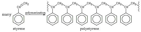
POLYSTYRENE GRADES
they are
General Purpose Polystyrene (GPPS)
GPPS has excellent transparency, good water resistance, and a high dielectric strength. It is widely used for laminated electronic circuits, high frequency insulation sheet.
High Impact Polystyrene (HIPS)
HIPS has good dimensional strength, balanced properties of impact strength and heat resistance, is easily machined, and is relatively low cost.
Advantages
transparent but available in various color, low cost, rigid, , easy to mould and good dimensional stability. Good electrical properties, low dielectric loss. Excellent resistance to gamma radiation, It is available commercially in both pellet and sheet form. Good process ability including blow and vacuum molding, thermoforming, extrusion or compression molding, and machining. Good
Disadvantages
Brittle, poor chemical resistance especially to organics. Susceptible to UV degradation. Flammable, low impact strength, and poor weather ability
Chemical Properties
Glass transition temperature: 100oC.
Amorphous density at 25oC: 1.05 g/cm3.
Molecular weight of repeat unit: 104.1 g/mol.
Styrene Content 0.0500 - 55.0 %
Butadiene Content 60.0 - 78.0 %
Blowing Agent Content 4.50 - 6.80 %
Physical Properties
ASTM D570 Water Absorption, 24 hrs (%) GPPS 0.06; HIPS 0.01
ASTM D638 Tensile Strength (psi) GPPS 7,500; HIPS 4,000
ASTM D792 injection molding tool temperature (celcius) GPPS 20-60; HIPS 10-80
ASTM D792 injection molding pressure (kgf/cm2) GPPS 703-2110; HIPS 703-2110
ASTM D638 Tensile Elongation at Break (%) GPPS 47; HIPS 55
ASTM D785 Rockwell Hardness GPPS M60-70; HIPS M10-80
ASTM D792 Molding Shrinkage rate (%), GPPS 0,4-0,7; HIPS 0,4-0,7
Others Properties
Max. Operating Temp. (°C) 50
Water Absorption (%) 0.05
Oxygen Index (%) 18
Flammability UL94 HB
Volume Resistivity (log ohm.cm) 16
Dielectric Strength (MV/m) 20
Dissipation Factor 1kHz 0.0002
Dielectric Constant 1kHz 2.6
Polyethylene or polyethene is a thermoplastic commodity made by the chemical industry and probably the polymer you see most in daily life. Polyethylene is a polymer consisting of long chains of the monomer ethylene, see about introduction to polymer structure of polyethylene. Polyethylene is created through polymerization of ethene. It can be produced through 3 methods
• radical polymerization,
• anionic addition polymerization,
• Ion coordination polymerization or cationic addition polymerization.
At this post you will learn radical polymerization of polyethene.
Radical polymerization
is a type of polymerization in which the reactive center of a polymer chain consists of a radical. then what is reactive centre
A reactive center in chemistry is a particular location, usually an atom, within a chemical compound that is the likely center of a reaction in which the chemical is involved. In chain-growth polymer chemistry this is also the point of propagation for a growing chain. The reactive center is commonly radical, anionic, or cationic in nature, but can also take other forms (wikipedia)
Technical scale
The necessary pressure is generally kept around 180 to 350MPa and the temperature ranges from 180 to 350 C, The high-pressure polymerization of ethene proceeds via a radical chain mechanism. In this case chain propagation is regulated by disproportionation or recombination.
Radically created polyethene typically contains a total number of 10 to 50 branches per 1000 C atoms. Of these, 10% are ethyl, 50% are butyl, and 40% are longer side chains, Intermolecular and intramolecular chain transfer take place simultaneously
To prevent self-degeneration,
the temperature should not exceed 350C. Ethene
and intitiator are introduced by a piston or membrane compressor. An in-built sapphire window makes it possible to observe the phase relation. After the polymerization is finished, the reaction mixture is released in two steps. Temperature increases are due to a negative Joule Thompson effect. At 26MPa, ethene separates from the 250 C hot polymer melt. After further decompression down to normal pressure, the residual ethane is removed
Initiation
Initiation is the creation of free radicals necessary for propagation. The radicals can be created from radical initiators, such as organic peroxide molecules, or other molecules containing an O-O single bond or by reacting oxygen with ethene, the polymerization reaction is initiated by three classes of free-radical initiators,
Oxygen or peroxides are used as the initiators. Initiation is very similar to that
in many other free-radical polymerizations at different temperatures according to their half-live times. based on handbook of polymer synthesis, below is half time table of peroxide initiators
you also can see online simulation of radical polymerization by the following link
reference :
http://en.wikipedia.org/wiki/Radical_polymerization
http://pirika.com/chem/PolymerE/naoko2.htm
http://www.univie.ac.at/mmphc/pp_num.html
HANDBOOK OF POLYMER SYNTHESIS,Hans R. Kricheldorf : 2005
plastics divided in two large kinds, they are thermoplastic and thermosets, in general, thermoset materials are stronger than thermoplastic materials due to this 3-D network of bonds, thermosets materials can not be softened on heating. In thermosetting polymers, the polymer chains are joined (or cross-linked) by intermolecular bonding, cross linking is what makes thermosets special.as we know thermoplastics can be re molded and made into other products. Thermosets, once cured, can not be transformed into another shape, their chemistry has been permanently altered.
History
Goodyear discovery of the vulcanization
of natural rubber in 1839 could be construed as the first successful commercial
venture based on thermosetting polymers. The plastics industry dates the
beginning of thermosetting plastics to the development by Leo Baekeland in
1909 of phenolic.
The Historical Milestones of Thermosets
1839 Goodyear discovered vulcanization of rubber.
1909 Baekeland granted his heat and Pressure・ patent for phenolic resins (Thermoset polycondensate)
1926 Alkyd introduced. Aniline-formaldehyde introduced in U.S.
1928 Urea-formaldehyde introduced commercially.
1931 Hyde began research on organo-silicon polymers.
1933 Ellis patented unsaturated polyester resins.
1935 Henkel made melamine-formaldehyde resins.
1937 Automatic compression molding introduced commercially. Polyurethanes first produced.
1938 Melamine formaldehyde introduced commercially. Used in molding compounds and food containers.
1939 First patent on epoxy was found in Germany
1941 Urethane-polyester type-introduced in Germany.
1942 Dow Coming made silicone industrially.
1943 Castan patent issued on epoxy.
1943 Thermoset polycondensate. Silicone (SI) used in computer chips, IC, cooking ware.
1946 Polyurethane elastomers introduced.
1947 Epoxy introduced commercially, thermoset polyadduct. Used in reactive molding compounds. Also used in adhesives.
1954 Polyurethane introduced in U.S.
1957 Urethane-polyether type-introduced in U.S.
1964 Polyimides introduced as a fabricated product.
Definitions
various definitions has explained by scientist, specially because the bond type of this polymer. Here some definitions
Thermosetting plastics (thermosets) are polymer materials that cure, through the addition of energy, to a stronger form. The energy may be in the form of heat (generally above 200 degrees Celsius), through a chemical reaction (two-part epoxy, for example), or irradiation.(wikipedia.org)
Goodman and Schwartz define thermoset as
a polymeric material which can be formed by the application of heat and pressure, but as a result of a chemical reaction, permanently crosslinks and cannot be reformed upon further application of heat and pressure
A polymer-based liquid or powder that becomes solid when heated, placed under pressure, treated with a chemical or via radiation. The curing process creates a chemical bond that, unlike a thermoplastic, prevents the material from being remelted (http://www.techweb.com/)
Resin or plastic compounds which in their final state as finished articles are substantially infusible and insoluble. Thermosetting resins are often liquid at some stage in their manufacture or processing,
which are cured by heat, catalysis, or other chemical means. After being fully cured, thermosets cannot be resoftened by heat. Some plastics which are normally thermoplastic can be made thermosetting by means of crosslinking with other materials. (Whittington Dictionary of Plastics)
Categories of Thermosets
based on individual families of plastic and the purpose we can divided thermosets as
1. General purpose
Phenolic, amino's, polyesters
2. Engineering Purpose
Epoxy, polyurethane
3. Specialty purpose
Silicones, allyls, high temperature thermosets, cross linked thermoplastic.
Thermosets Processing Methode
thermoset can be processed by molding, the kind of molding that can process thermosets are :
Injection Molding
Extrusion Molding
Compression Molding
Casting methode
( see the each explanation of those mold here)
the advantages of thermosets
Thermosets have many advantages:
* Excellent thermal propeties (epoxy)low creep over time.
* Excellent strength to weight ratio
* Rigid, Excellent fire performance,flame retardant.
* Cost competitive against metals & engineering thermoplastics
* No absorption of water
* Dimensionally stable at high temperatures
* Reliability
* High impact strength
* Electrical & thermal insulation properties
* Anti-stain / FDA applications
* Can achieve tight tolerances
* Withstands environmental extremes
* chemical and Corrosion resistant (epoxy)
* easy processed in low cost method and technology


